Exporting CAD to Geospatial File Types
MicroStation design files are rich in geometry types. This wide variety of geometry includes points, lines and polygons as well as arcs, ellipses, b-splines and text. 3D files may contain surfaces and solids. Further these data types can be combined into other types. For example, dimensions are composed of lines, text and possibly symbol text. All of these data types are well known and are required to represent the complex content found on the average design sheet or engineering model. These various data types can also exist on the same level, effectively appearing to OpenCities Map as the same feature.
A common example is a roadway alignment. This typically consists of a linear feature showing the alignment but also text indicating station numbers, cross ticks indicating the station markers. In some cases text representing curve data is also shown on the alignment level. To an engineer this makes sense as all these components make up the alignment information.
But to perform an analytical operation, perhaps creating a buffer to be overlaid with wetlands information, the only information that is relevant is the actual alignment itself.
Most Geospatial data types support points, lines and polygons only. When OpenCities Map exports features it converts the various MicroStation geometries into one of those types. In addition, most geospatial data types do not support display symbology. This means that the MicroStation design file will likely look very different in the receiving application. However, it should be geometrically correct, except for those cases where conversion of curve elements to lines (stroking) is involved.
| MicroStation element | Geospatial data type |
|---|---|
| Cells, Text | Points |
| Lines, linestrings | Lines |
| Arcs, b-splines (stroked) | Lines |
| Shapes, multi-sided shapes | Polygons |
| Ellipses (stroked) | Polygons |
Text and cells are translated as points in the resulting output file. That means the receiving user will not see the text value or what the actual symbol looks like in MicroStation.
Lines and polygons generally transfer very well. The exception is when there are curves or arcs in the linear or polygon element or when circles or ellipses are transferred. These are stroked into line strings using a defined tolerance. This tolerance is defined by the OpenCities Map variable ECSDK_GEOMETRY_STROKING_TOLERANCE. It represents the maximum distance between the actual element and the approximating line in master units.
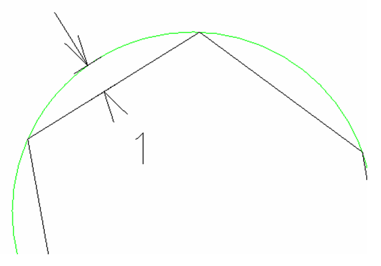
The figure below represents a stroking tolerance of 1 where the original curve is the green arc and the approximating line is black. In practice, a much smaller stroking tolerance would yield better results.